3060ti 16GB Possible?
May 2025
STATUS: DOESN’T WORK. 2 MEMORY CHANNELS DISABLED AFTER CHANGING STRAPS. WORKING ON CUSTOM VBIOS
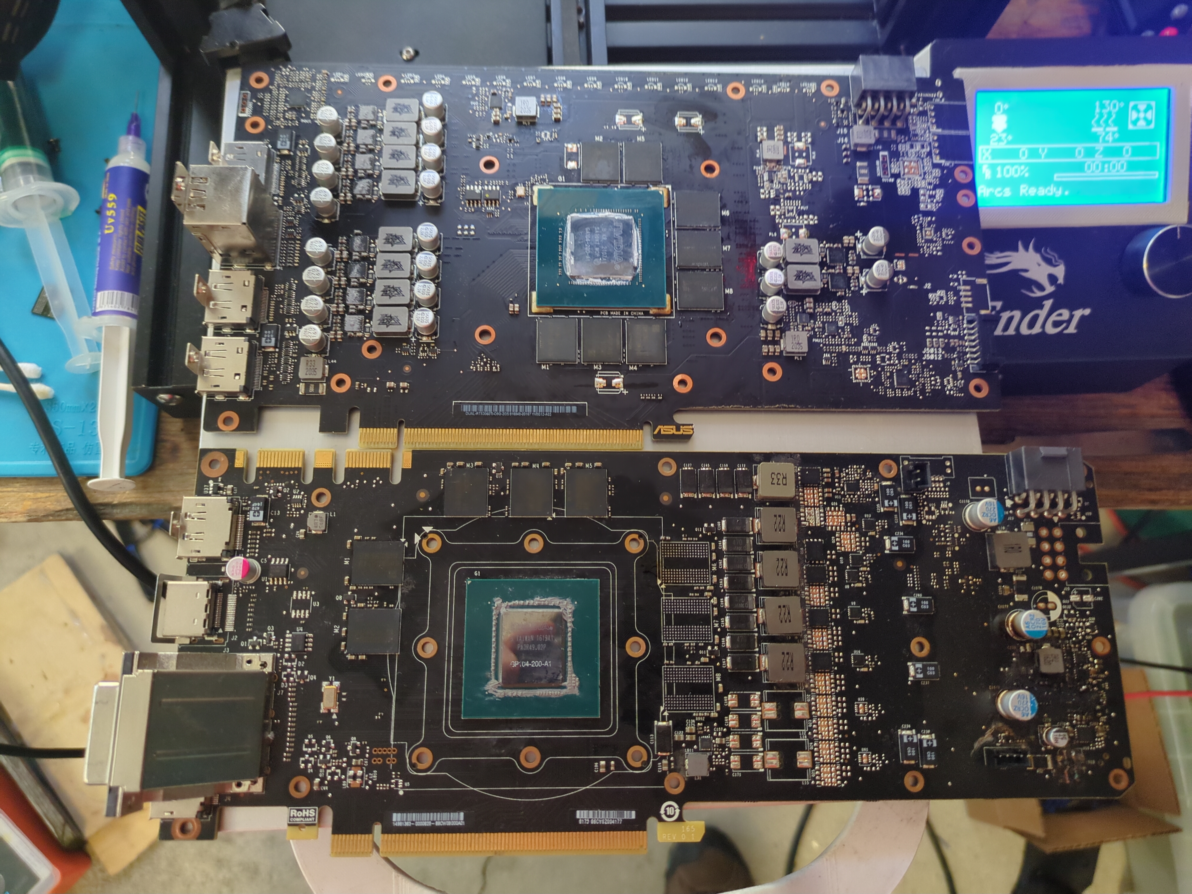
Making a 3070 16GB is possible, but what about 3060ti 16GB? I like to run LLMs locally for privacy reasons, also get to play with model settings and RAG. The issue is always never enough VRAM. 3060ti stock has 8GB, so you are limited to 7B models. I can run 14B Q4 on my system or else it gets way too slow. First step, buy the VRAM on Aliexpress. My card shipped with 8x 8gb Samsung GDDR6 K4Z80325BC-HC14. I need 8x 16gb Samsung GDDR6 K4ZAF325BM-HC14. I bought 9 on Aliexpress for around 100CAD just in case I destroyed one. Next, I practiced removing exactly 26 memory modules on broken cards before attempting. I had some old GTX 670s I found in the dump and 1070 with a bad memory controller.
Now when desoldering the VRAM, you must preheat the board because just hot air is not enough. Lead free solder melts around 216C, so you need a lot of heat. Remember the PCB acts like a heatsink, pulling that heat away from the area you are working. If you force the chip out BEFORE everything is molten, there goes all the pads on the PCB. I didn’t have a preheater, so I improvised and used my 3D printer heat bed. But before that, I needed to flash custom Marlin firmware onto the board to increase the max bed temperature to 130C. Very easy, just modify the Marlin firmware, compile, and flash to board like an Arduino. Of course Im using a Creality Ender 3 with a 8bit Sanguino board, but do whatever you need to do to get a hot surface at least big enough to fit the card.
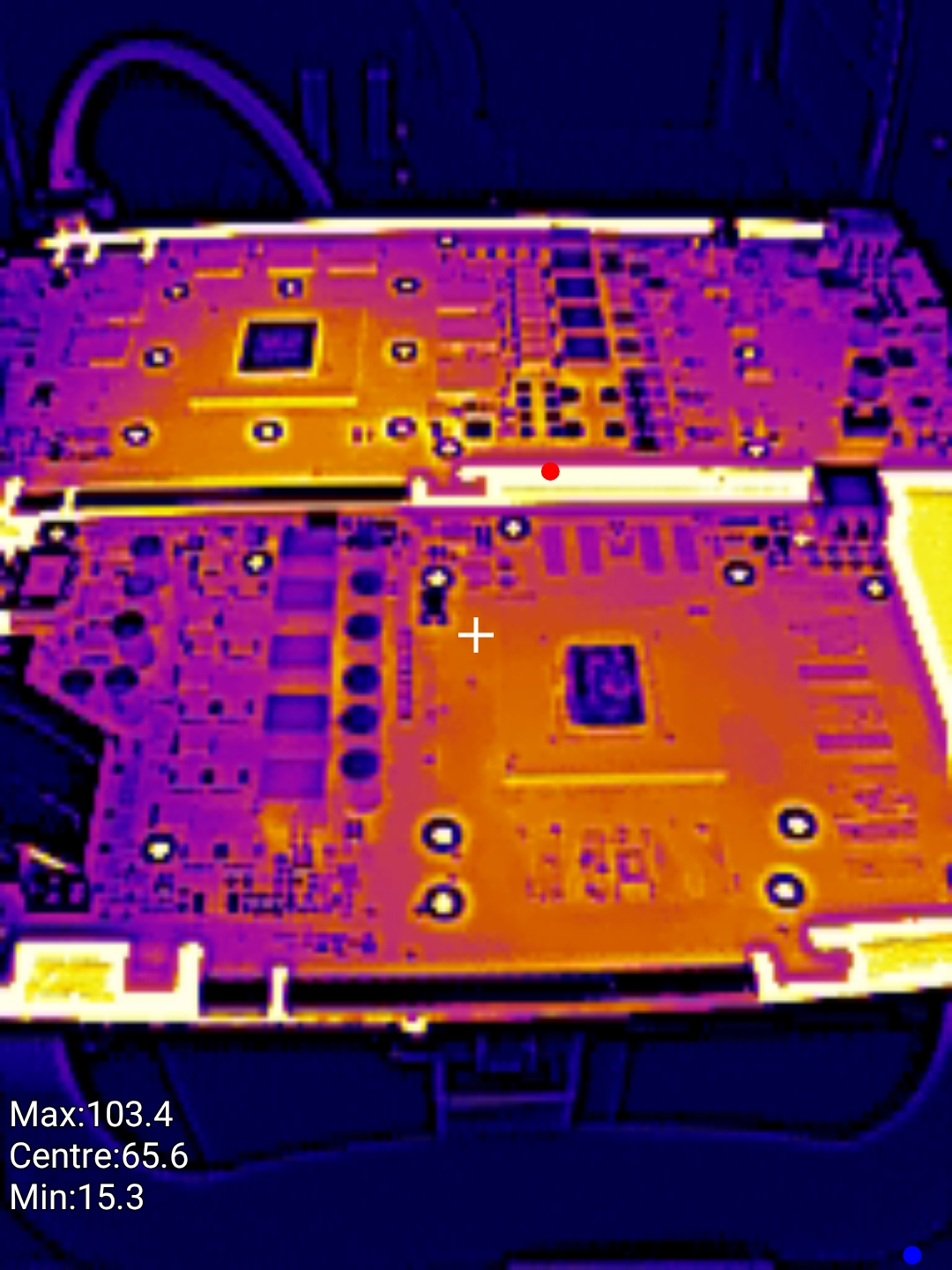
Put the board on the preheater and leave it there for 10-15 minutes. Let it slowly get up to temp. I got my thermal camera out and took these cool images:
TLDR: FLUX AND PATIENCE IS YOUR FRIEND
It took me 2 days 3 hrs of practice each until I got comfortable with removing memory chips and cleaning the pads. With the board preheated, add flux to the side of the VRAM, then use hot air at 450C to heat directly on top of the chip. Move the hot air around so you aren’t overheating a general area. If there are capacitors close by, put aluminum foil to shield it or any metal object to cover it. You don’t want an exploding electrolytic capacitor. I stopped using aluminum foil tape because it always left a residue on the board that was a pain in the a** to clean up, so now its just aluminum foil. Kinda a pain in the a** to put it over the component and make it stay there, but it works.
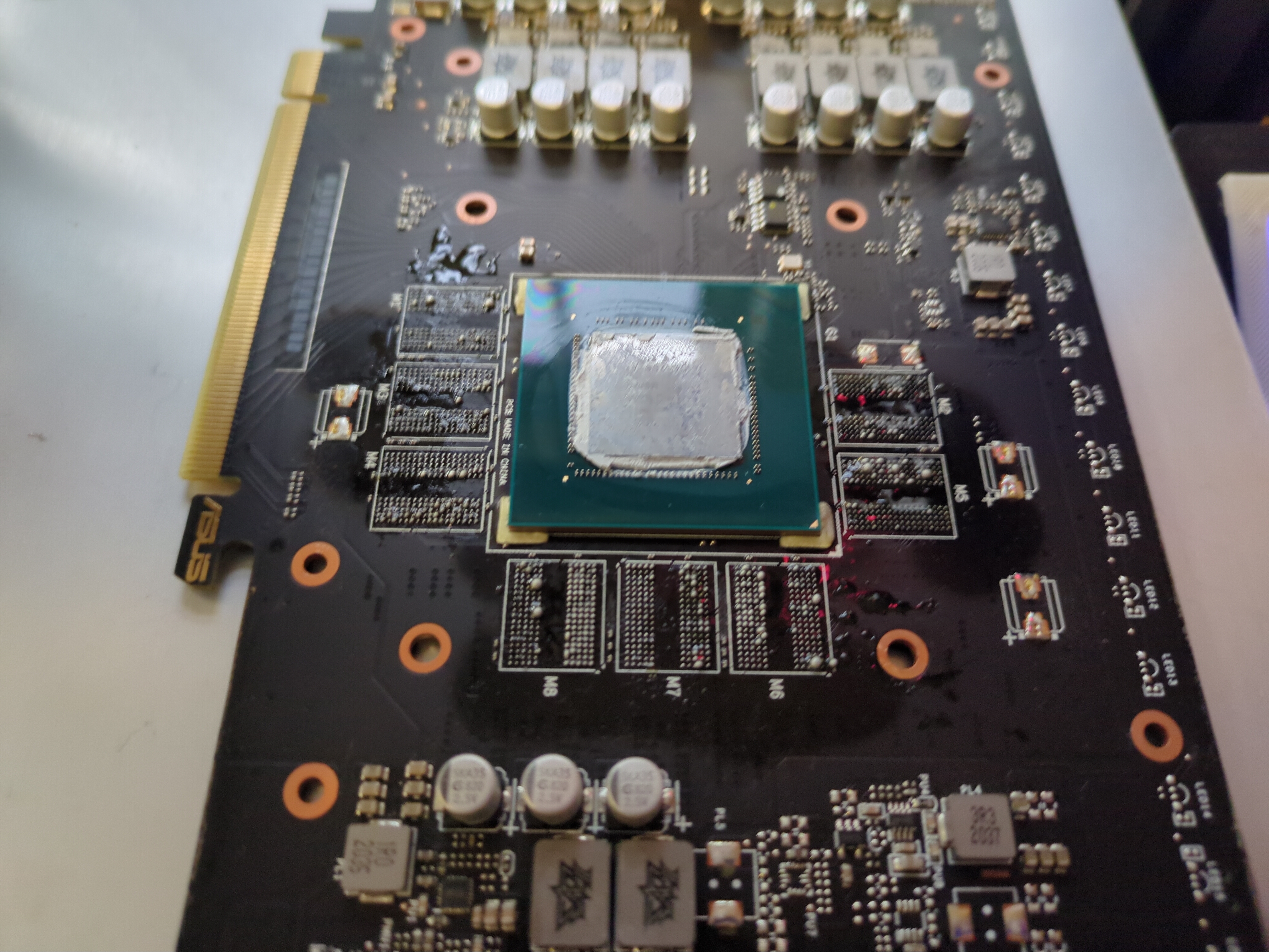
Tap the side of the chip occasionally after the flux mostly boils away. This depends on the flux, but I noticed after it stopped smoking so much, the solder is near liquid. And yes use a fume extractor because there will be LOTS and LOTS of flux fumes. You will smell like flux after you are done. When the solder is fully molten, the chip should move when you tap it. Heat the chip for 5 more seconds, then carefully slide the tweezer underneath the chip, and slowly lift up and away. There were tiny 0201 capacitors next to the chips and I only knocked off one. Just be very patient and carefully lift the chip. Of course, keep the hot air over the chip while you are doing this. A video is a thousand words, so watch GPU Solutions video to see how its actually done. This is what the 3060ti looked like after:
Once you are done, the most stressful part. Removing old solder and cleaning pads so they are nice and flat. Remember we are working with BGA packages. The new VRAM comes already reballed from the factory. Put flux on the pads and drag your soldering iron with a ball of leaded solder on it VERY CAREFULLY over the pads. My soldering iron doesn’t even touch the board. Just get a huge blob of leaded solder on the tip and hover it over the pads, soldering iron at 420C. This way you are sucking up all the lead free solder, replacing with leaded, and making the desoldering process easier since leaded solder(60/40) has lower melting point at around 187C. This way you are introducing minimum pressure on the pads, minimizing the chance of ripping a pad. If you rip a pad and its a data channel, its game over.
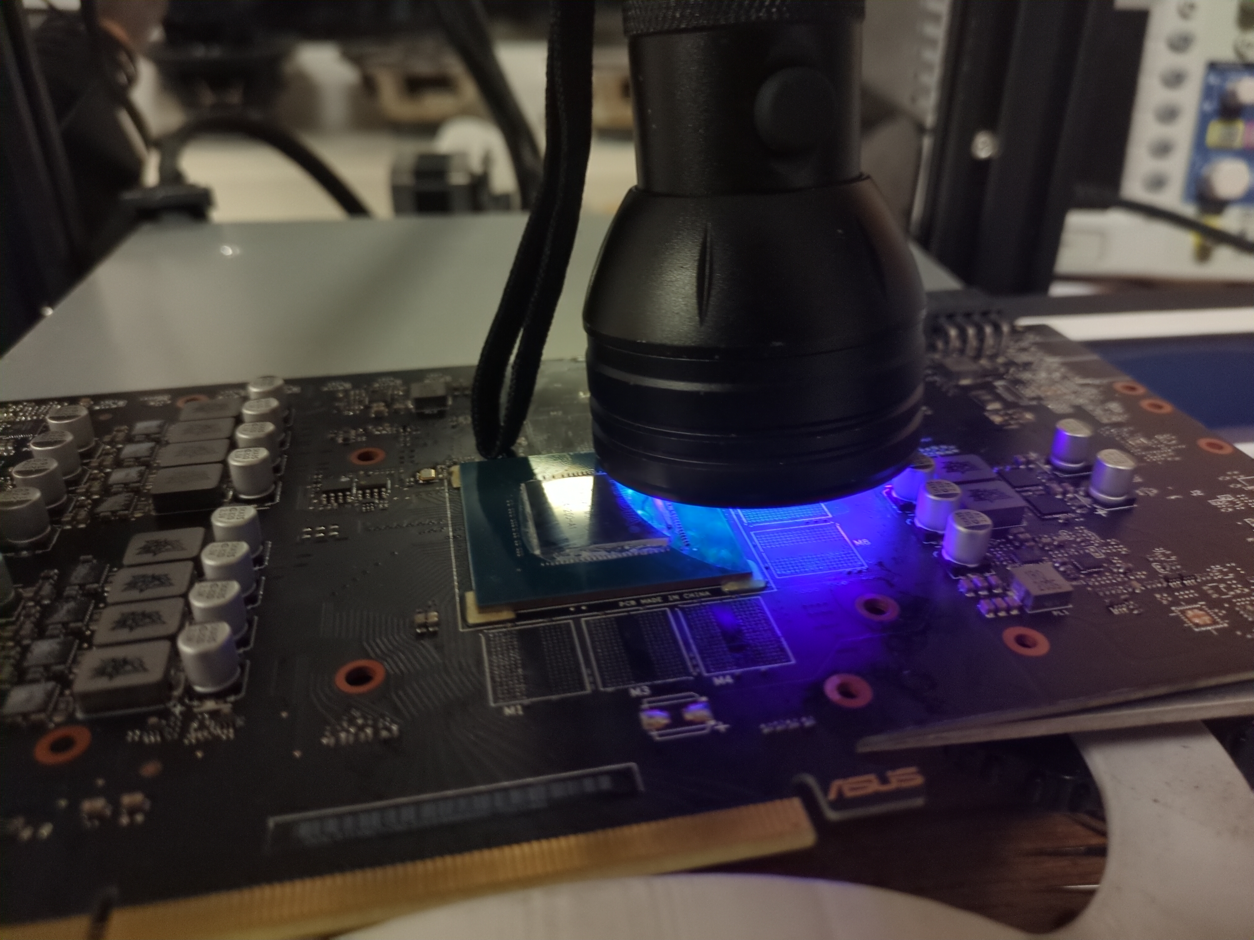
Then use a GOOD quality desoldering wick. I recommend 1-1.5mm Goot wick, but this time I am trying out Chipquik 1.5mm desoldering wick I bought on Mouser. Its a very stiff wick and needs lots of additional flux. I only had 3mm Goot wick, too wide. Just make sure to trim it constantly, so you are not oversaturating the wick. Put more flux on the pads and CAREFULLY drag the soldering iron over the desoldering wick. Put minimum pressure. GPU Solutions should go over it in his video. MAKE SURE to practice this on a dead card and hone your technique so you don’t rip any pads. It helps to use a VERY THICK tip so it has a lot of heat mass. Remember, keep the board on the preheater so its less work for your soldering iron. Now even after being super careful, I damaged some tracks on the memory. Inspect it carefully under a bright light. I used some UV green solder mask and applied a SUPER thin coating on the damaged tracks in between the pads. Don’t put too much or the new chip won’t sit flat. This prevents accidental solder bridges when resoldering, then leave it under a UV flashlight for 5 minutes or however long it takes for the coating to cure. MAKE SURE to clean the board from ALL flux before you do this, so it sticks well to the PCB.
Now we are finally ready to solder the new memory chips. The PCB has markings for where Pin 1 is. DONT GET THIS MIXED UP or the memory won’t work. Clean the pads THROUGHLY with isopropyl 99% and qtip + toothbrush. Remove as much old flux and debris as you can. Put a thin layer of flux on the pads. Since the board is still on the preheater at this point, the flux should turn liquid. Don’t put too much or the chip can actually move and bridge solder balls when the excess flux boils during soldering. I didn’t learn my lesson until I messed up because of this. What I recommend is to put some on the pads, then spread it with the metal nozzle of the flux dispenser. Make sure it covers all the corners. It should not overflow too much outside the corners of the chip reference designator. Finally place and align it as best as you can with the dot on the new VRAM to pin 1 mark on the reference designator on PCB. It doesn’t need to be perfect because the molten solder will pull the chip naturally into place.
Once all the chips have been placed on the PCB in the CORRECT orientation WITH a thin layer of flux under EACH ONE!!! Use hot air at 450C to reflow into place. What I found worked best is to heat further away for around 30 seconds, then move in close to the chip. Look at the side of the chip while you do this. You will see the chip fall down into place as the solder melts. Once you see this, keep your hot air for 5 seconds longer, then CAREFULLY tap the side of the chip with a pair of tweezers. It should move, then fall back into place. This ensures all solder is molten and the chip is in the correct position. Repeat this 8 times. TLDR:
- Set preheater to 130C and preheat PCB for 15min.
- Put flux around each memory IC.
- Hot air at 450C apply heat and tap side of chip with tweezers. Once the chip moves, use tweezers to carefully lift the chip with upward motion.
- Put more flux on pads.
- Soldering iron at 420C, make a huge blob of leaded solder on tip and hover over the pads to remove old leaded solder. The soldering iron shouldn’t touch the pads at all.
- Put more flux on pads.
- Use desoldering wick 1.5mm and carefully clean pads by dragging soldering iron with minimum pressure over pads. Cut off used wick as you go.
- Clean all pads with isopropyl 99% + qtip + toothbrush.
- Put a THIN layer of flux. Don’t put too much or you risk bridges as the flux boils and has no where to go during soldering.
- Put the new chips on the board. Make sure the orientation is correct. Match the reference designator on the PCB!!!
- Hot air at 450C and apply heat until you see chip fall down. Tap side of chip and it should move out and back into place if solder is molten.
- Finally, clean flux with isopropyl while board is still hot.
At this point, don’t celebrate too early yet. We need to test the installed memory to ensure it has been soldered correctly. Your GPU won’t detect 16GB just yet, we need to set straps, which we will do after testing. Clean as much flux as possible and let the board naturally come down to temperature. You don’t want to risk too quick temperature changes or the layers in the PCB might delaminate. Hasn’t happened to me, probably lower risk since most GPU boards are good quality, but keep this in mind. I turned off the preheater and just left the PCB on there for 20 minutes. After just put the heatsink on with the four screws. We need cooling for the GPU since it gets very hot during testing. The tool we are using is MATS. You flash MODS.img first using dd or Rufus, then put the version of MATS/MODS you want to use. You can download a later version of MATS/MODS here. Yes I know its a self signed cert, not hosted by me. Just go to the Files tab and select NVIDIA.