UPS
I found a free APC BackUPS 1500 at the e-waste bin at University. Plugged it in to test and of course battery is shot. This UPS uses a 24V 9aH battery, which is quite weak to my tastes, I want to upgrade to a much bigger one. Of course, it is important to understand the risks of doing this. First, this UPS has no active cooling, so don’t put a 100aH battery in there and expect it to continuously provide ~900W for 2 hours, it will probably overheat and MOSFET explodes!!! Next, charging the battery can take a very long time, haven’t measured the charge current, but assume these UPSs use a CC method to charge batteries.
I plan on replacing the batteries with 2 12V 18aH LiFePO4 in series. This will give my 24V @ 18aH. The original UPS had 2 SLA batteries in series. Downsides to SLA batteries is much lower charge cycles(~500) compared to LiFE(~2000+) and a lower discharge limit(~50% of capacity), reason is even deep cycle SLAs can have their lifespan significantly shortened if you discharge them fully. With LiFE, this is no problem, so a 18aH LiFE is roughly equal to a 36aH SLA battery since you can fully discharge them without ruining their lifespan. A downside to LiFE is the higher charging voltage, I will try to reprogram my UPS first to see if its even possible. Remember its a horrible idea to use car batteries. First, they are flooded, which means you need to top them up and there is a risk of hydrogen production(NICE!!). Second, they are not designed for deep cycle applications such as a UPS, so they will die very quickly.
Welp after some reconsideration, I decided to purchase 2 SLA batteries 35ah. The reason is the ups I have is not the Smart series, so I am unable to program anything with a serial port. This means I can’t change the battery float voltage, this needs to be higher for LiFE batteries.
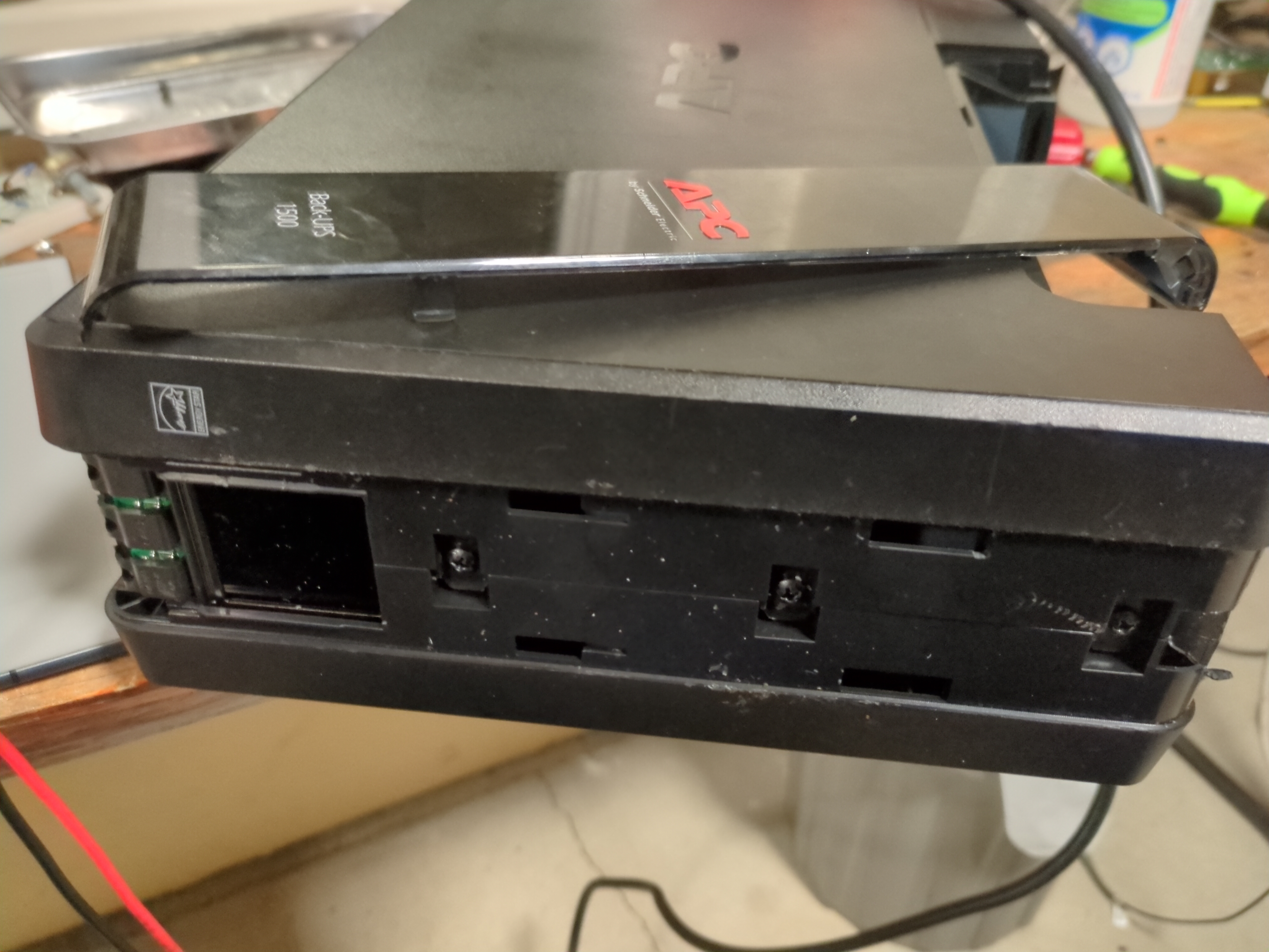
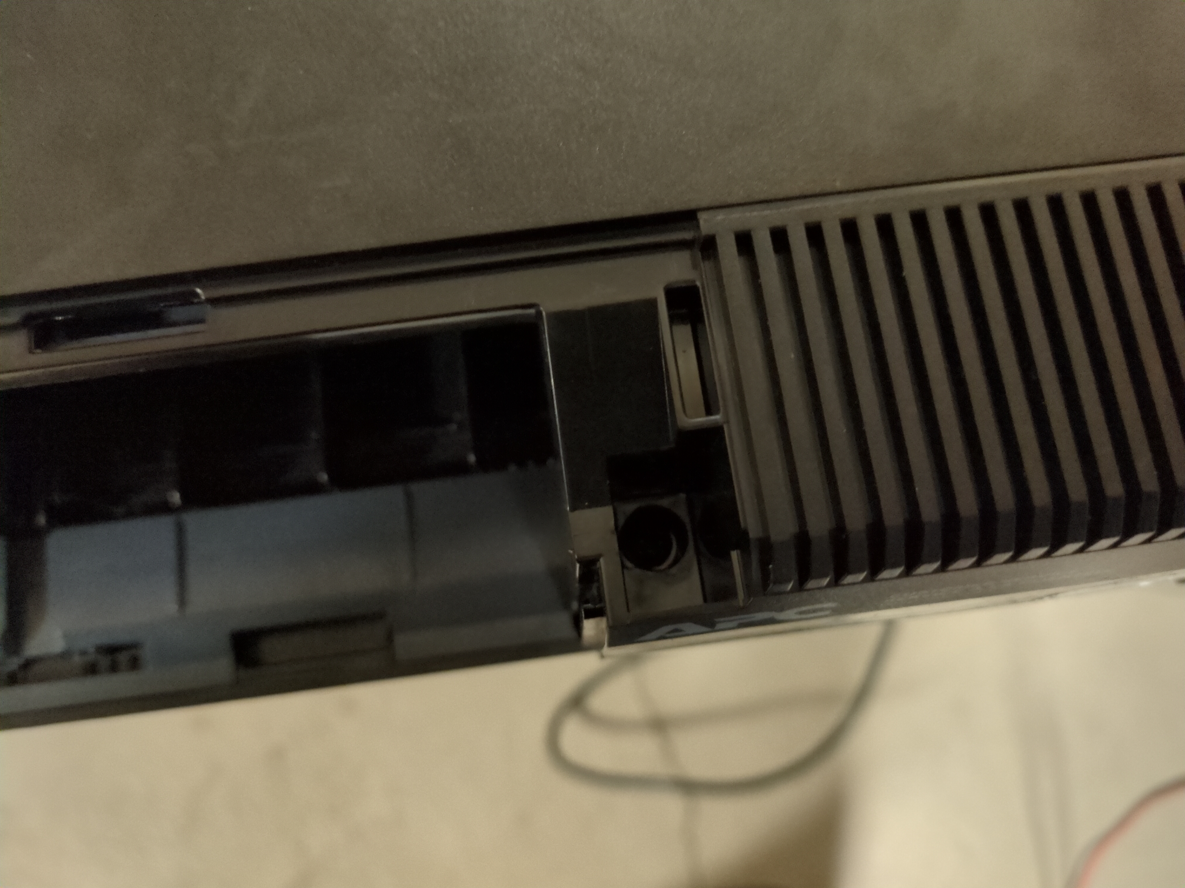
I want to open and inspect the UPS for any damaged internals before I put this into production. Good practice to do this with all equipment you find for free. There were 3 hidden screws behind the front plastic cover. Use a screwdriver or opening pick and start from the bottom and work your way around. Don’t pry from where the buttons are because that will break the plastic. There was also another hidden screw near the battery door, make sure you remove that.
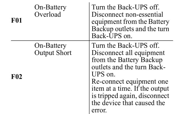
Wiggling the case and pulling up on both sides, I was able to seperate the case and see the internals. Upon initial inspection, everything looks good, no black marks on the pcb, so I applied 24V using my PSU to simulate a battery.
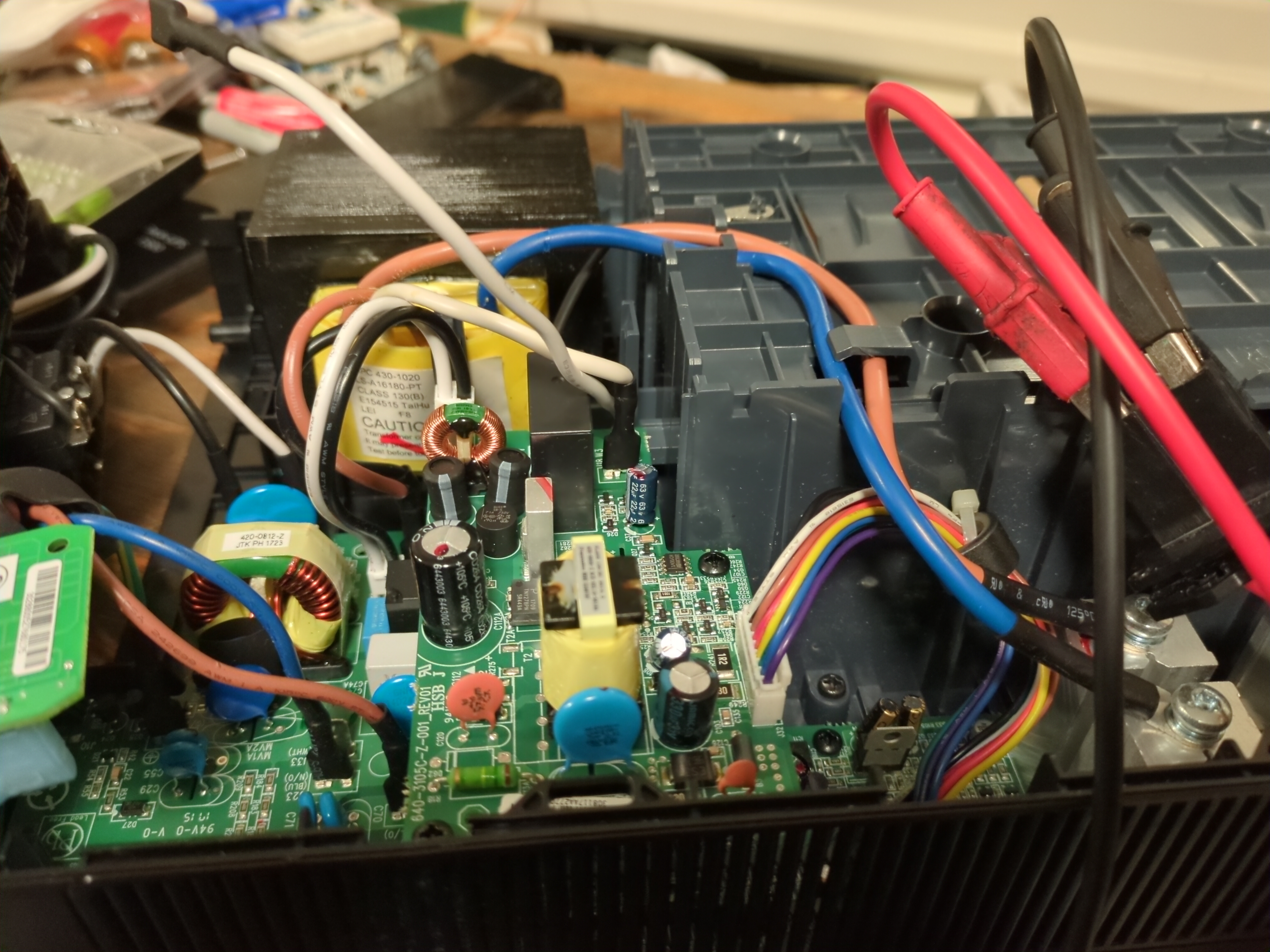
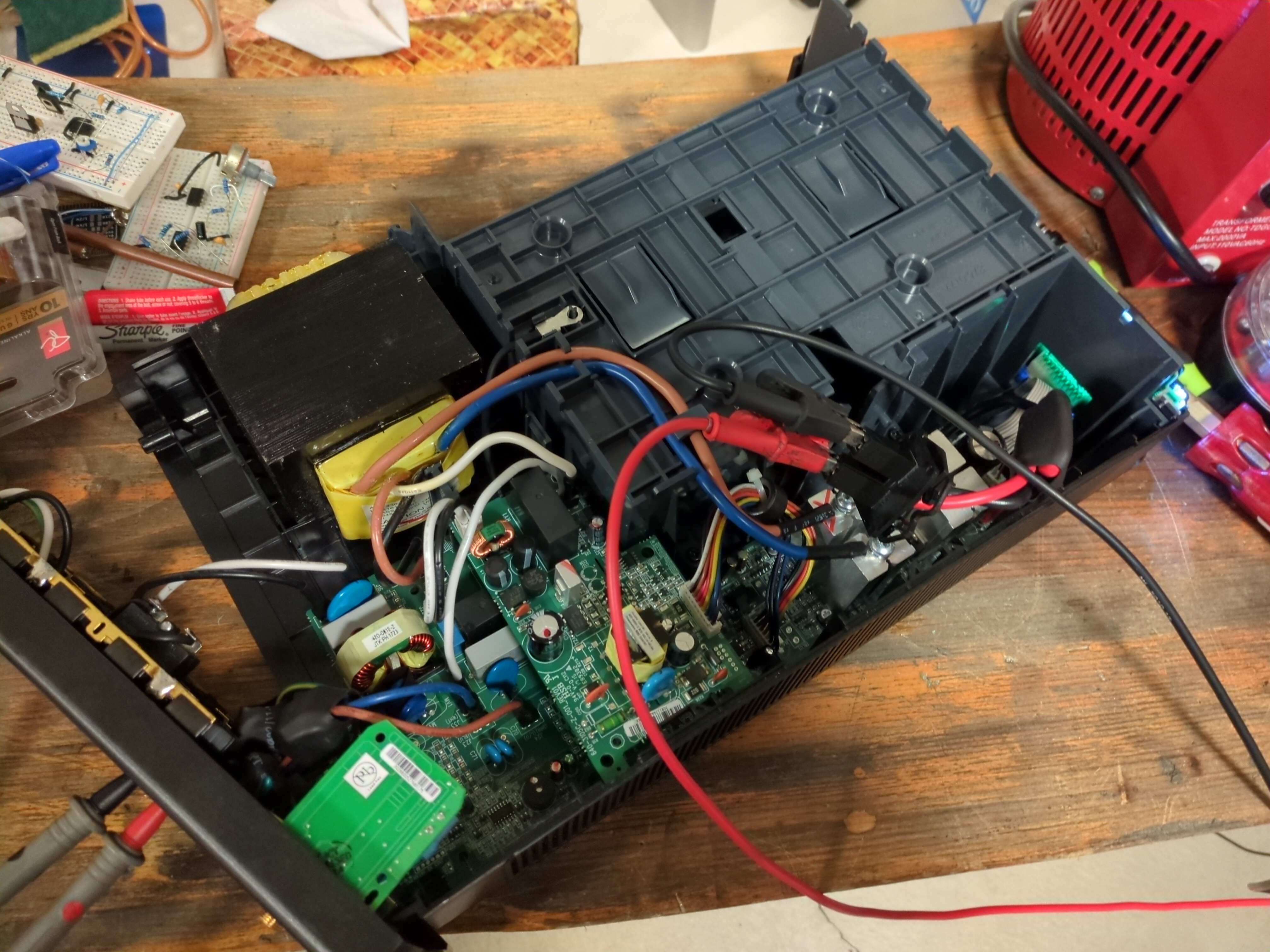
I pressed the power button and UPS immediately starts to beep with error code F02. Quickly shutting everything off, I consult the manual.
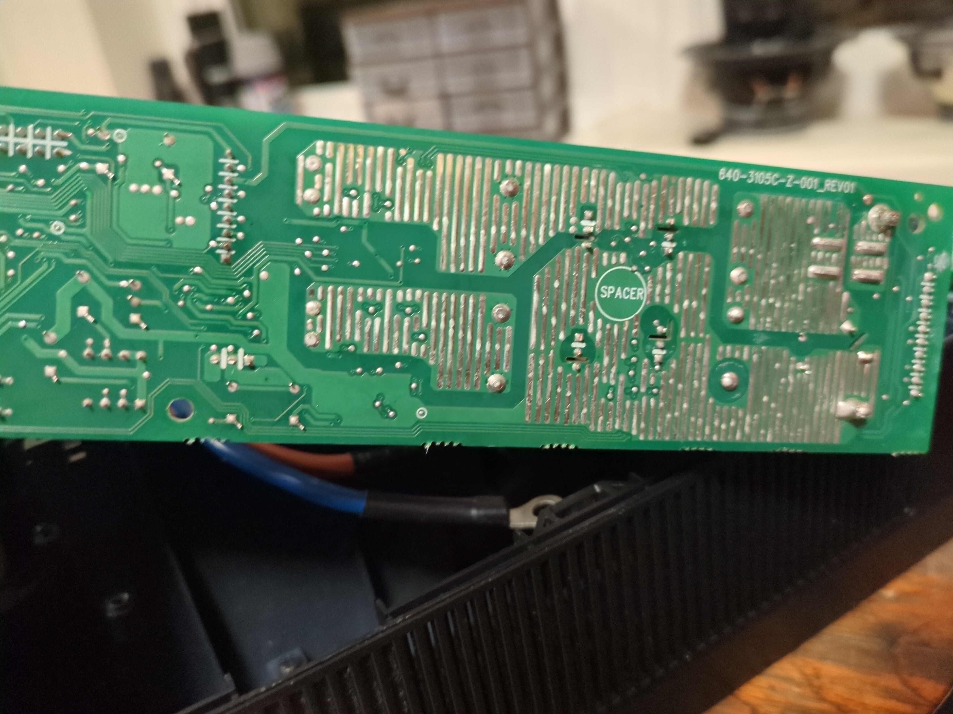
Ok so I have on battery output short. I use my multimeter in continuity to check for short circuit on the output outlets and nothing. Then spent the next hour checking for short circuits on capacitors on the PCB, still nothing. Took the PCB out and checked the H bridge MOSFETs from Gate-Source, and Source-Drain for the body diode. Everything checks out fine. Eventually, I went on the internet and someone mentioned a weak battery also causing this issue. Now my power supply is set at a current limit of 500mA, I increased this to around 1A and no more beeping!! The UPS drew a CC of 700mA and I can hear a 60HZ hum from the huge transformer. Measuring the output, I see 110V, a bit low but its working. I have confirmed the power electronics work, now I need to make sure I can interface with the UPS via USB. I plan on using this UPS to safely shutdown my Proxmox server during a power outage.
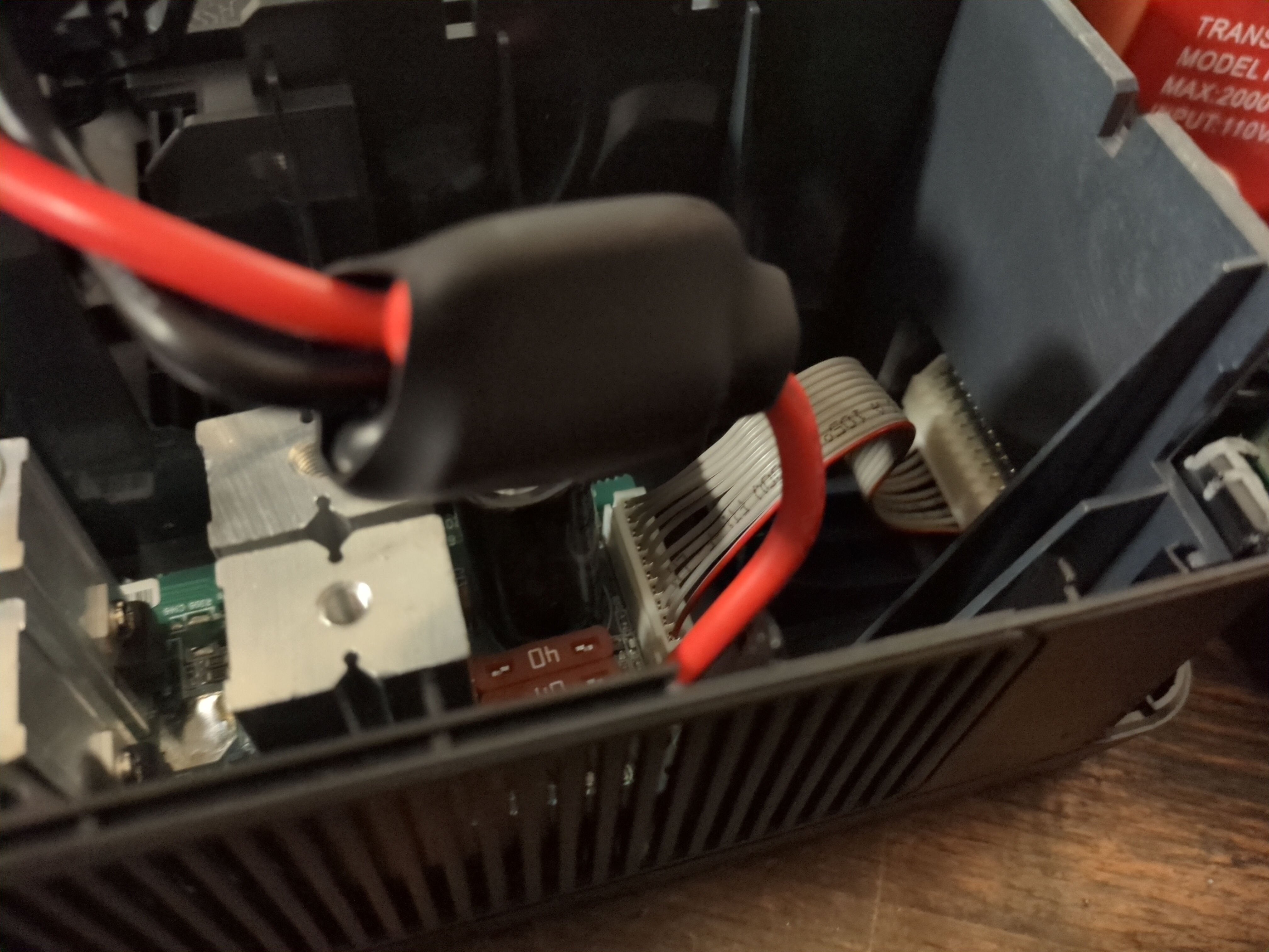
Unfortunately, this UPS doesn’t have a USB port, but uses an ethernet port. WHY??? Cmon APC just use a bloody USB C connector… Anyways, I needed to figure out the pinout so I can make my own connector because I am not paying the 30 dollars for a new one. A bit of searching and I found this website showing me the pinout of the connector. Of course APC had to use a RJ50 connector instead of RJ45, so I needed to solder jumpers to the PCB.
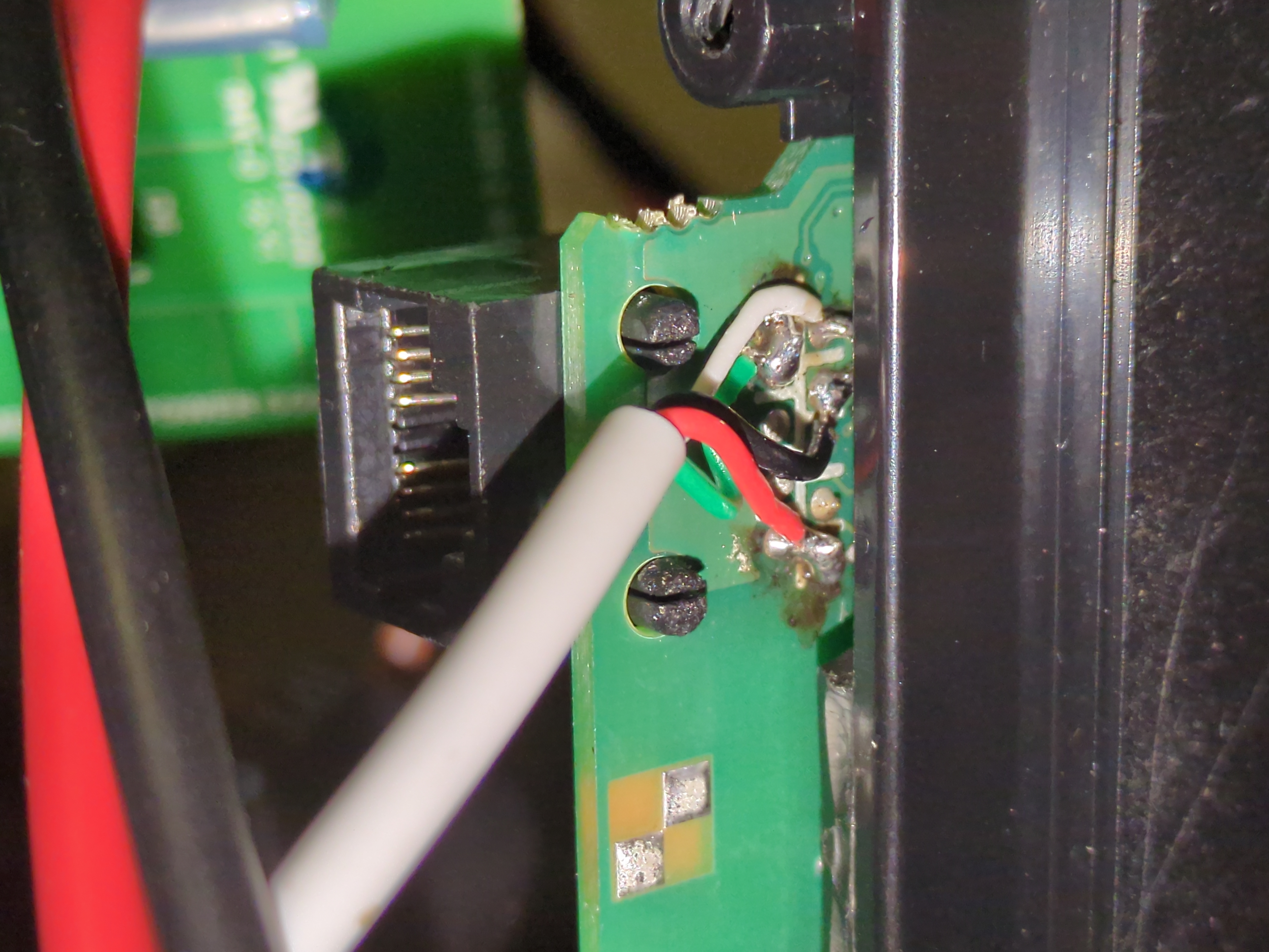
The connector size is the same as RJ45, so I can use a standard ethernet connector and crimp in a USB cable. Since I cannot access the most left and most right pin of the connector, I needed to jump them to other pins. Thankfully, not all pins were used for data communication, only 4/8 are used. Pin 1(most left) is +5v and Pin 10(most right, counting all slots) is D+. Remember I can only access pins 2-9 with a standard RJ45 connector. I soldered Pin 1 -> Pin 2 and soldered Pin 10 -> Pin 8.
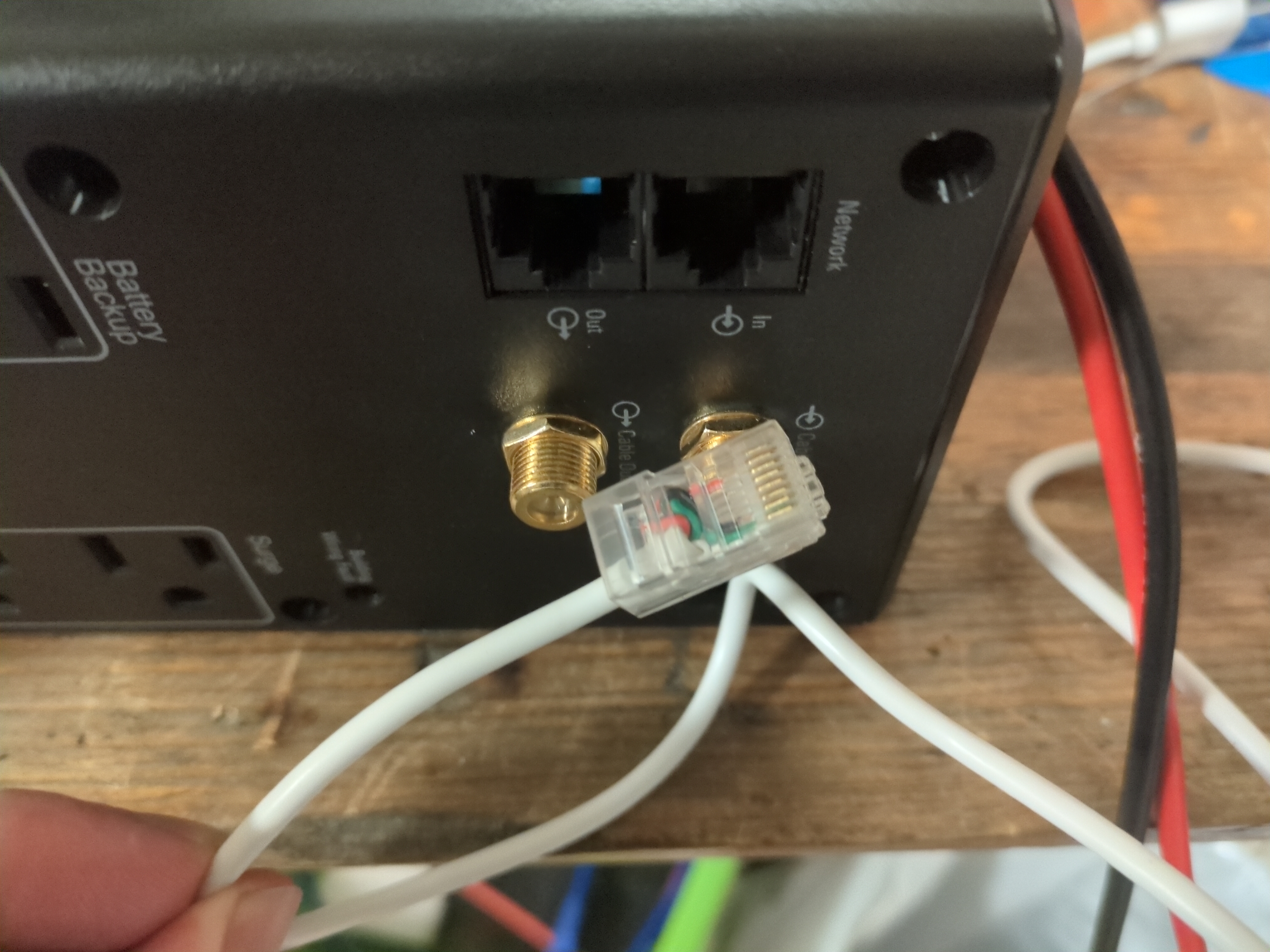
This is how I crimped my USB cable to the ethernet port, for black wire you can use either pin 3 or pin 6:
    1 -> +5V
    2 -> NC
    3 -> GND
    4 -> X
    5 -> X
    6 -> GND
    7 -> D+
    8 -> D-
After 5 days of waiting, finally got both my batteries I ordered A WEEK AGO. To be fair, Canada Post strike backlogged everything, but cmon just deliver both the packages at the same time!!! Anyway, I immediately got to work, first step is make all the connectors and fuses.
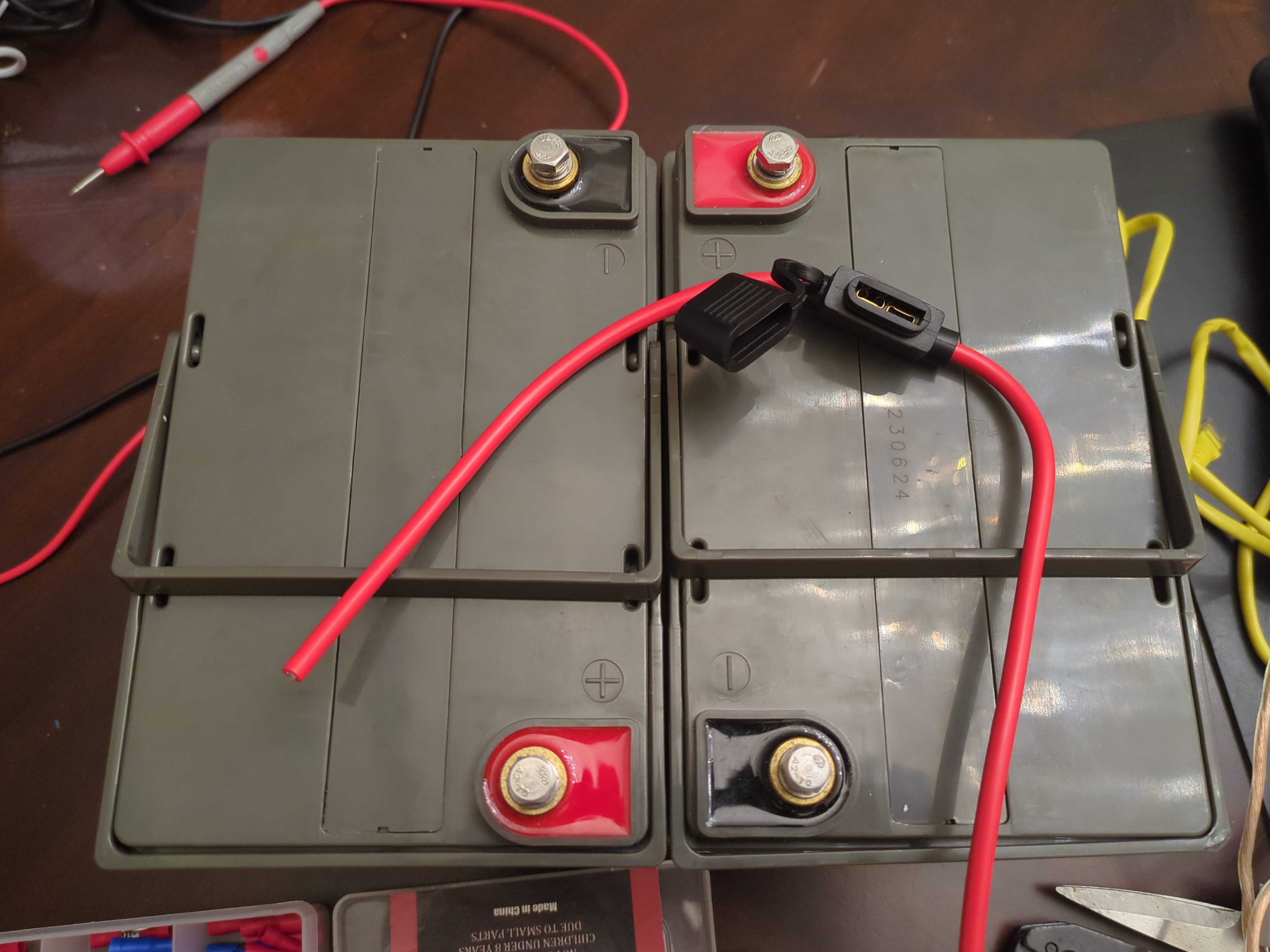
I ordered a 40A fuse connector to put in the series link between the 2 batteries. This will protect the wires if anything shorts and prevent a fire. These batteries can deliver lots of current, so you gotta be careful. I trimmed the wires down so it would fit better. Its important to use the thickest and shortest COPPER wires. This will reduce resistance and make the UPS last longer on battery. Also it reduces heat buildup, so keep your wires as short as possible. Make sure you use a good crimper and tug on the wire afterwards, it should be rock solid and shouldn’t just pull right out.
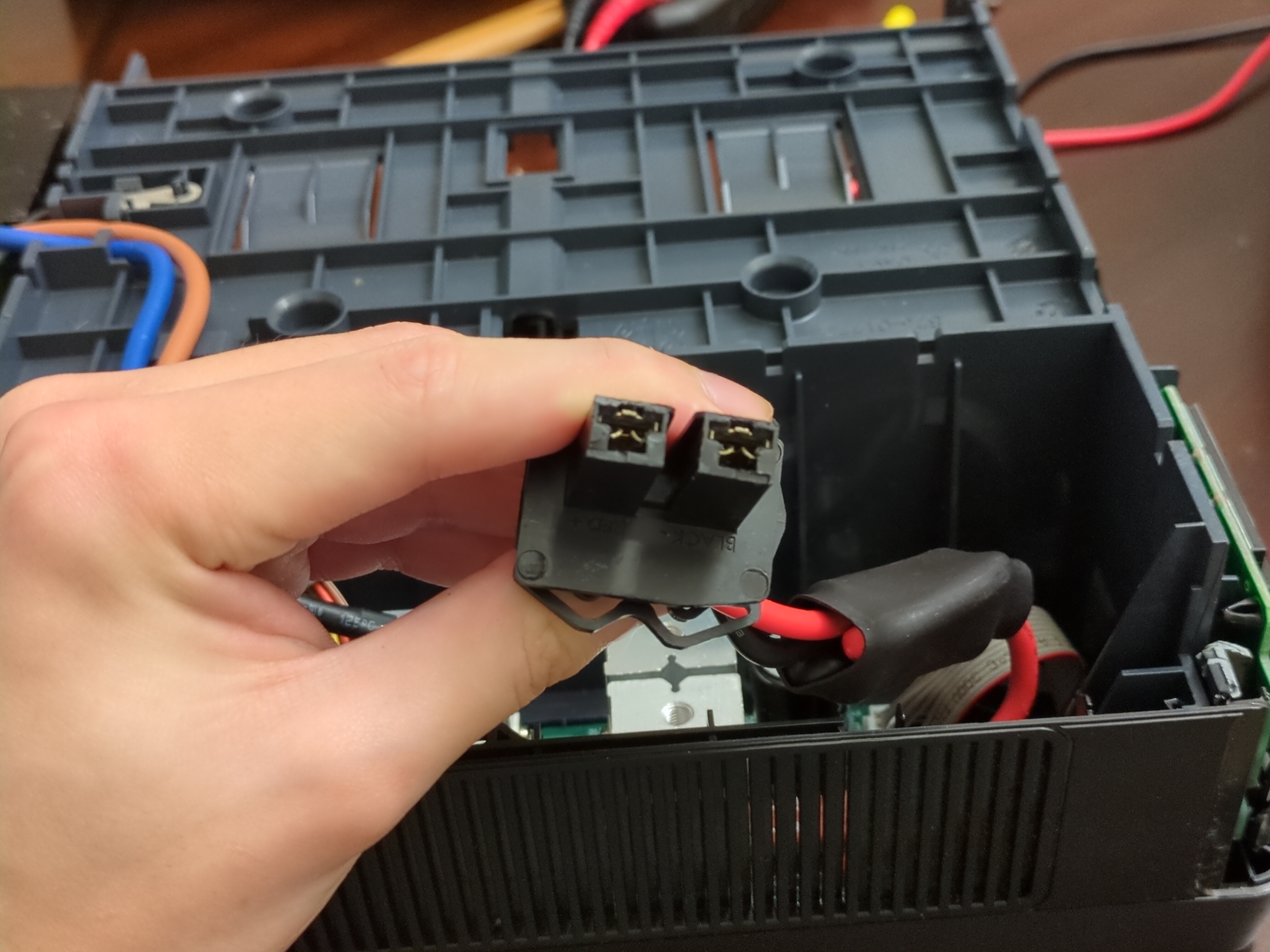
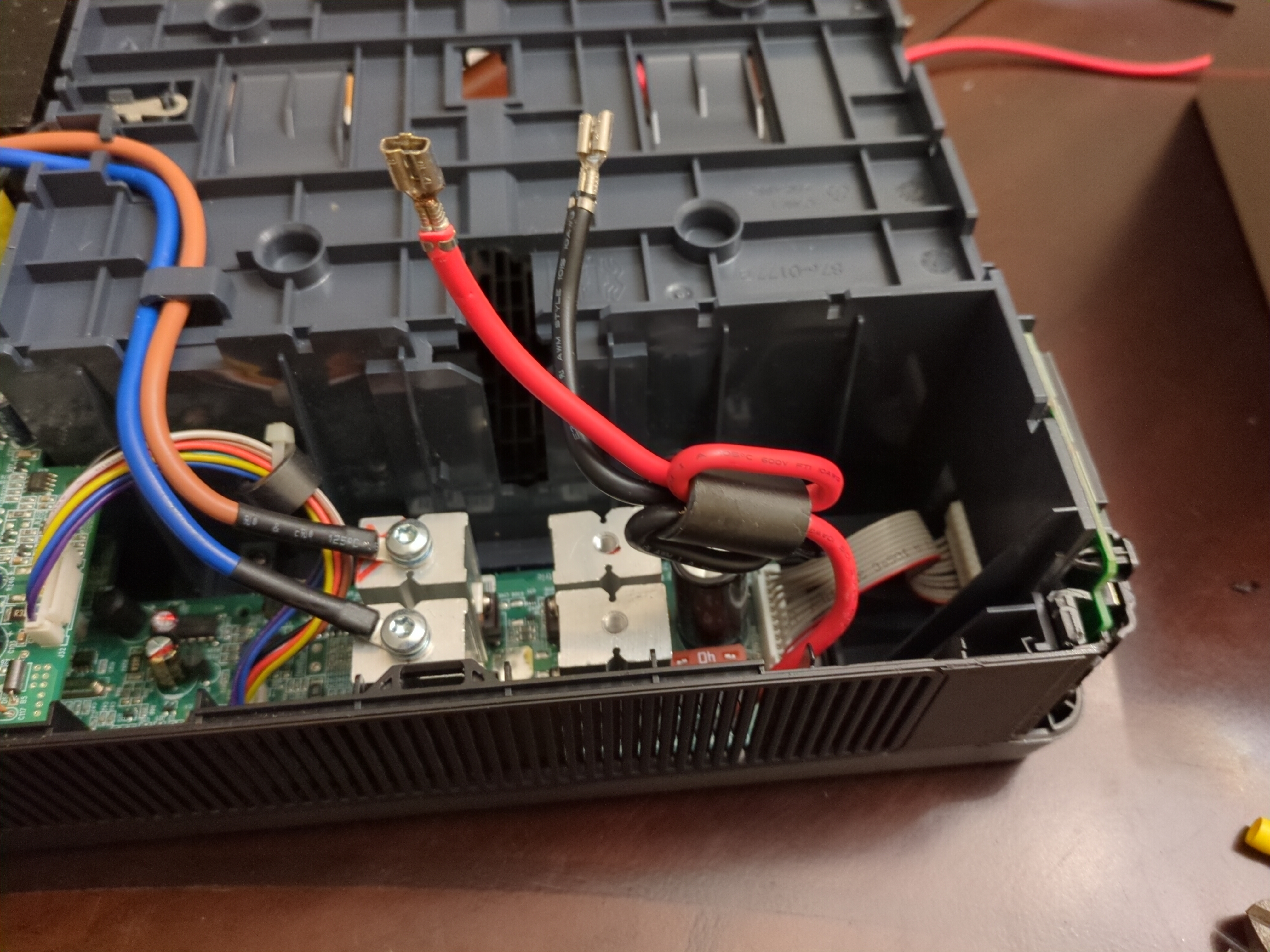
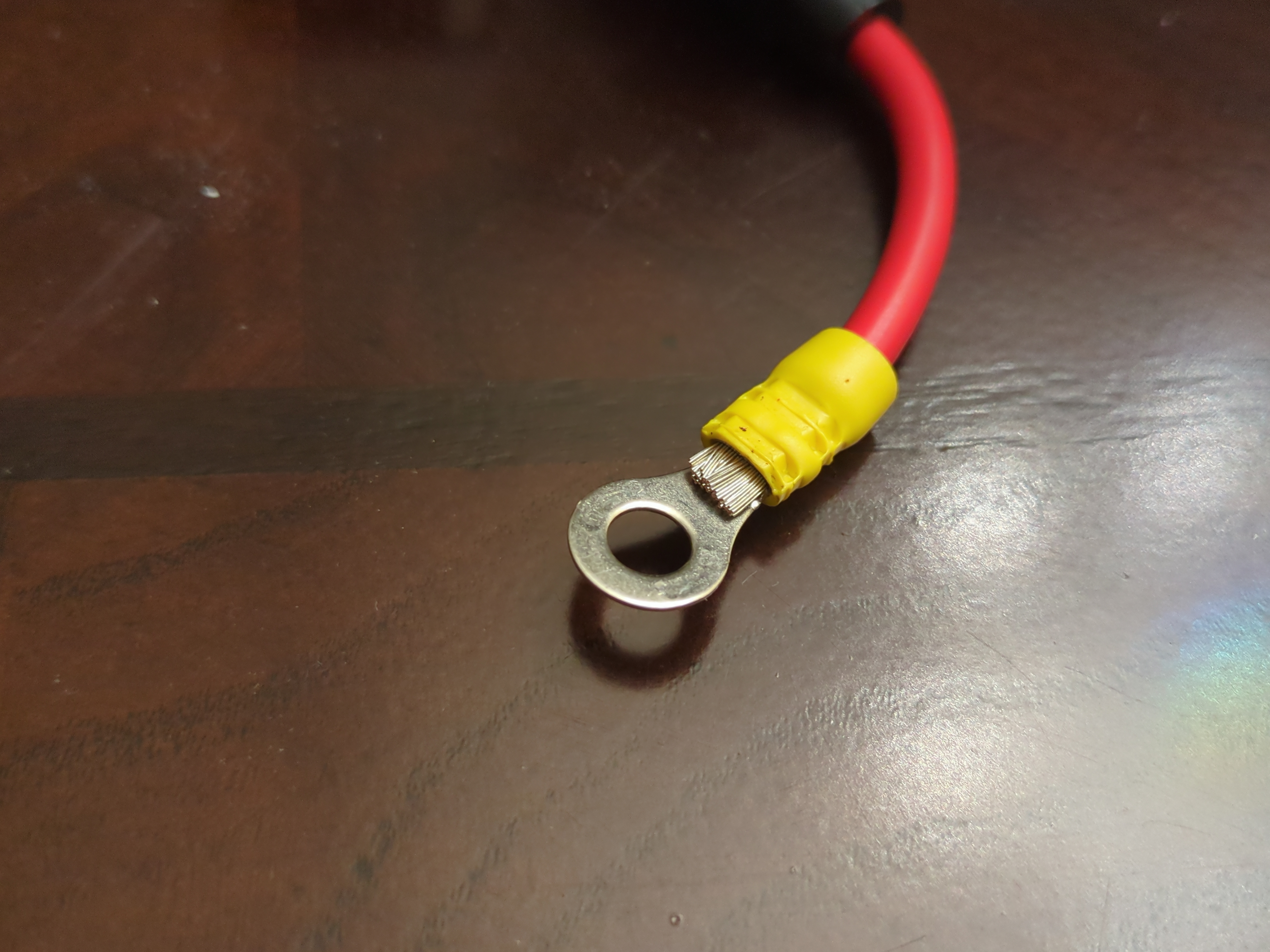
Next, I needed to attach new connectors on the battery connector. I want the battery connections to be removable. There are 2 locking tabs on the inside of each connector, use a screwdriver to push them outwards. The wire then slides out backwards out of the cover. Next, I removed the common mode choke. Not sure why they put one on the DC side, guess its to reduce external noise? But again, the original batter was internal. Anyways, I just cut off the connectors and pushed the wires out of the ferrite, a bit tough since they were in there tight. Then I cut, stripped, and recrimped a male connector on the UPS side. This side is uninsulated. The battery side will use insulated female connectors, shown in right figure. This is important to prevent short circuits and exciting fires. I used 12 gauge speaker wire for the battery cables, not ideal, but they won’t be moved around much and I will keep the wires seperated. The important bit is they are 100% copper wires, so less resistance and heat. Color code your connectors so you don’t mix them. I used a black sharpie to colour the negative terminal.
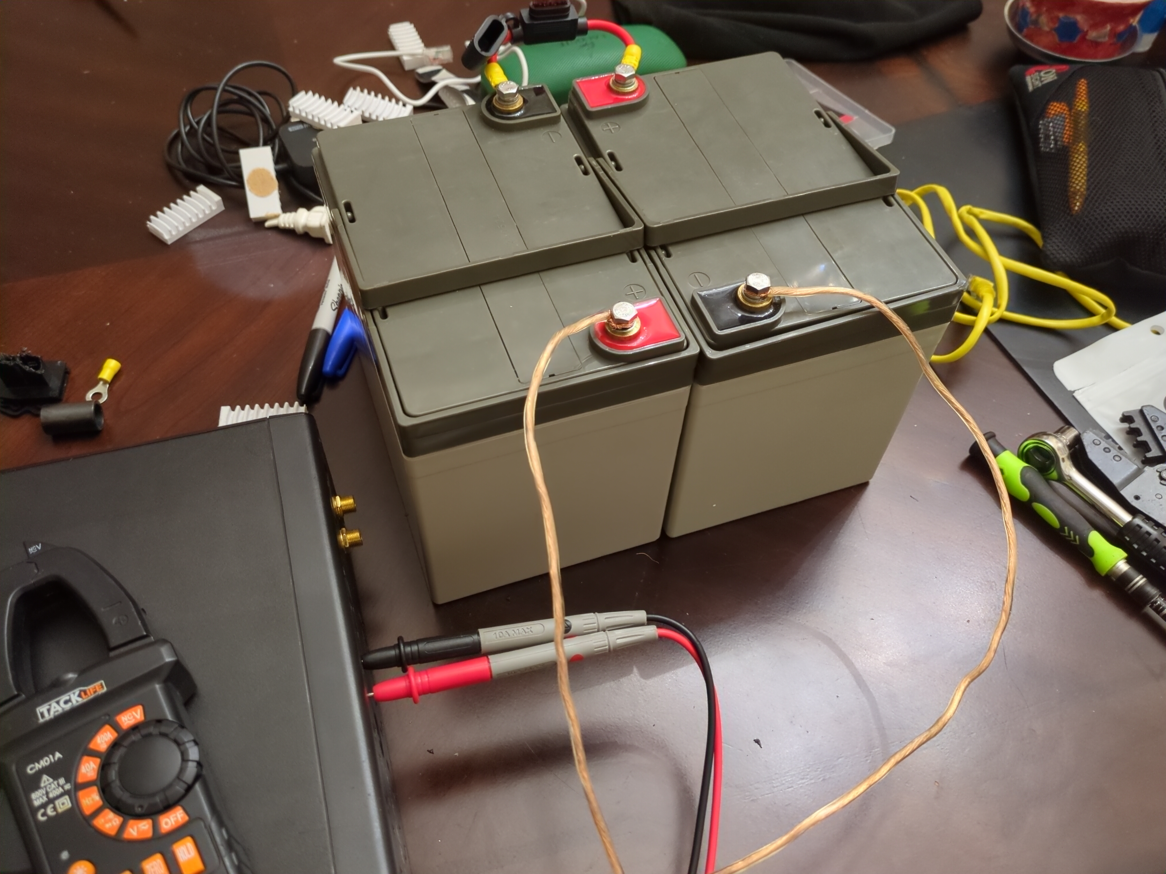
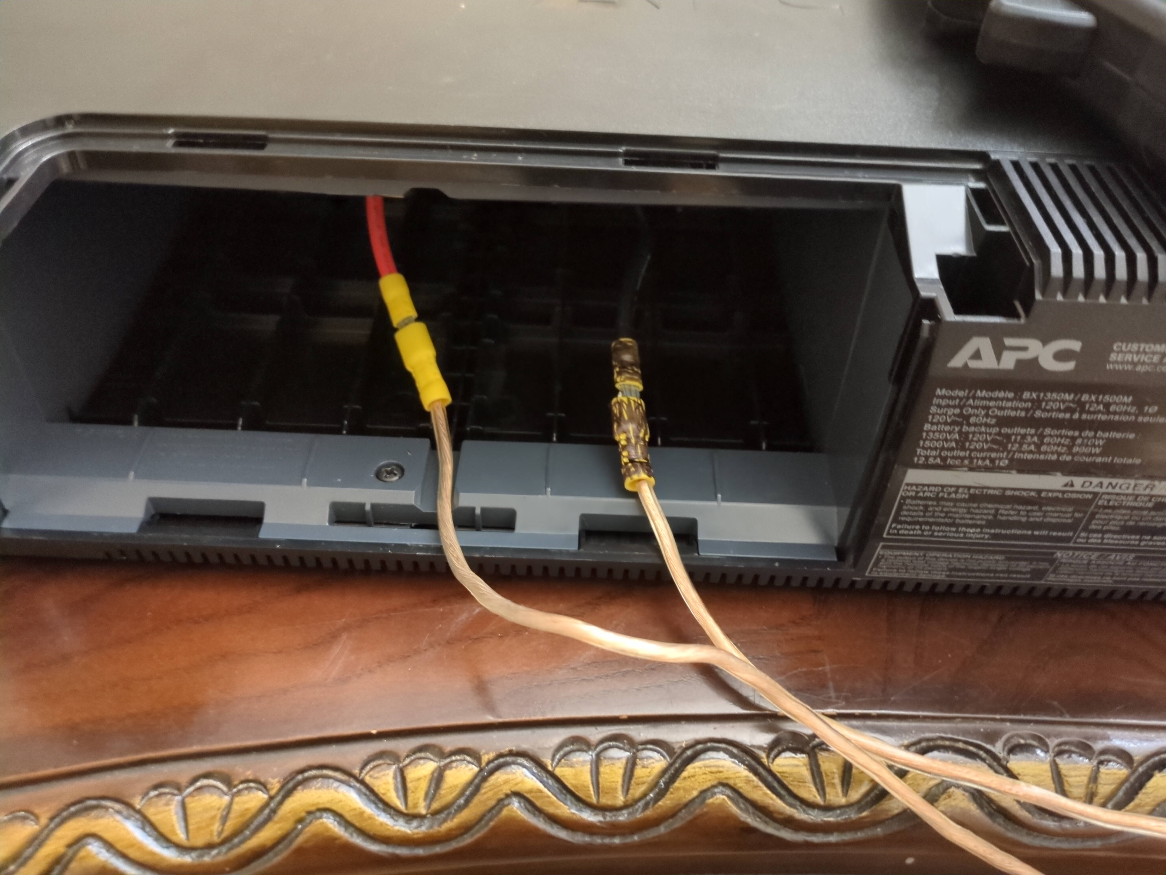
Alright lets plug everything in, hope no fire. I stripped and attached the other ends of the battery wires to the battery, tripping checking polarity. I grabbed my fire extinguisher in case anything horrible happened. Installed the fuse and there was a HUGE spark, scared the living sh*t out of me!! Thankfully nothing exciting happened afterwards. I didn’t notice the huge ass capacitor in parallel to the input, so when I connected the battery that thing drew a ton of current as it charged. In the future, power on the UPS, then connect the battery. There is 26V on the battery terminals with no battery connected, this precharges the capacitor so there isn’t a huge surge of current. Moment of truth, pushed the power button and BEEEEEP. UPS was online and outputing a 110V modified sine wave. Remember this isn’t a pure sine wave UPS, its the cheapest kind that outputs a sine looking square wave. Most switching PSUs handle this fine, but if you have very sensitive equipment, it might be wise to buy or find a better one that outputs an actual sine wave.
I plugged in the AC input to the wall and heard a relay click. I measured the battery charge current, 400mA. Expecting it to be low, remember this UPS is designed for a 9aH battery. Mine is 35aH, just less than 4x the original capacity. Assuming 80% charging efficiency and the battery was discharged to 50% capacity(SLAs should not be constantly deep cycled). Formula is: charge time = (battery capacity × depth of discharge) ÷ (charge current × charge efficiency) Source
Noice!! Over 2 days to recharge after discharging only to 50%. We don’t really care about charge time, more important is the actual runtime. I measured my homelab and it draws around 80-100W. Lets assume worst case scenario, so 100W constant load. Calculating the runtime is much harder, since the voltage is constantly changing. Lets just assume a CV of 24V. Roughly current would be:
\[4.166666667 A = \dfrac{100}{24}\]Very rough runtime:
\[4.32 hrs = \dfrac{35 \cdot 0.5}{4.166666667}\]Lets round down to 4 hrs runtime, since there will be efficiency loss. Not bad, much better than the 15 minutes if I used the original 9aH battery.