Music with Computer Hardware
Thanks to Paweł Zadrożniak, Device Orchestra, MrSolidSnake745, ArcAttack!, Franzoli Electronics, and many other smaller creators for inspiration and ideas for this project. This blog may not even have existed if these awesome people didn’t exist. Please check out their content and subscribe.
Making sounds with stepper motors is nothing new. If you own a 3d printer with no silent stepper driver(A4988), you will already be familiar with this. What if we managed to control the exact frequency of these sounds by pulsing the motors at a specific interval(440 times a second)? This is exactly what is happening and is the fundamental building block to tone generation with any electronic device with a stepper motor.
A floppy drive has a stepper motor that moves the read/write head back and forth along the magnetic tape on the floppy drive. Do you remember those noisy devices? What if we could somehow control the speed of the read/write head? Well we are in luck! If we take a look at the pinout of a floppy drive:
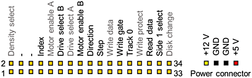
We notice 2 pins of interest called Step and Dir. These 2 pins allow direct control of the speed and direction of the read/write head. Unfortunately, before we can do anything, the drives must be enabled by pulling the Drive select A or B pin to ground. If the green LED on the front of the drive is on, the drive has been enabled. Now if we connect the step pin to ground, the stepper head moves a bit. By connecting the dir pin to high and ground, we can vary the direction of the read/write head. To power the drives, connect a suitable 5v power supply that can deliver at least 500mA to the +5v and GND on the floppy power connector. A computer ATX power supply with a floppy connector can also be used. A microcontroller interprets MIDI data from a computer and drives the floppy drives accordingly.
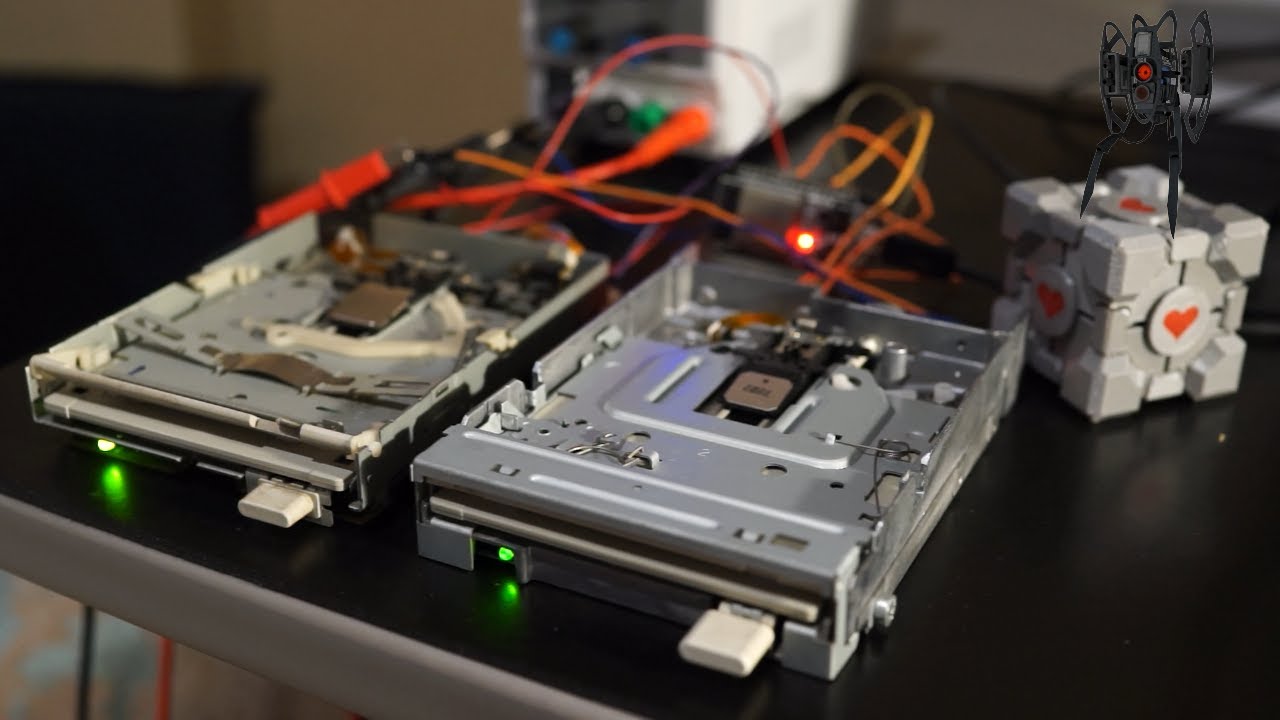
Here is a demonstration of 2 floppy drives playing Carra Mia Addio from Portal 2:
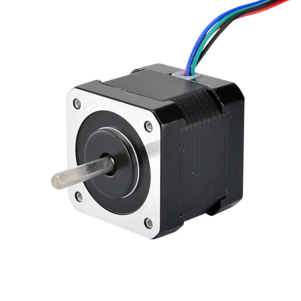
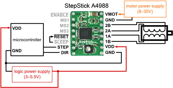
Driving stepper motors follows the exact same concept, although an external driver is used. I chose the A4988. The A4988 also has a Step and Dir pin just like the floppy drive. A stepper motor is different from a standard dc motor because it allows so much more control over the exact position of the motor. This allows it to be used in industrial applications such as robot arms or 3d printers as these motors can be controlled with extreme precision.
The A4988 is a complete microstepping motor driver with built-in translator for easy operation with minimal control lines. Carriers with these driver chips can be picked up quite cheaply on Aliexpress. If we take a look at a typical connection diagram, the only two connections to the microcontroller are the DIR and STEP pins. However, it is important to add a decoupling capacitor of approximately 47uF between Vmot and GND. The reset and sleep pins must be connected together to enable the driver. Additionally, the enable pin can be connected to the microcontroller to disable the driver when needed. The A4988 is a microstepping driver, so we can operate in full, half, quarter, eighth, or sixteenth step resolution. From my experience, running the driver at half step resolution for music allows for higher notes to be achieved, as well as less vibration.
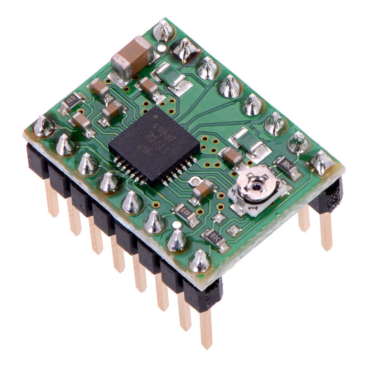
Operation of the A4988 is very simple, by pulsing the step pin at the frequency of a note, the motor will spin at that frequency. Here is some sample code and explanation(should work on majority of microcontrollers):
void loop() {
    digitalWrite(stepPin, HIGH);
    digitalWrite(stepPin, LOW);
    delayMicroseconds(2273); //2273us equivalent to concert A(440Hz)
}
To calulate the period, we need to some very simple math:
We know the period(T) is related to frequency(F) by:
\[T = \dfrac{1}{F}\] \[0.002273s = \dfrac{1}{440Hz}\]Converting from seconds to microseconds to use in the delayMicroseconds() function:
Therefore, we must pulse the step pin every 2273us in order to produce a 440Hz note. Unfortunately, this is an example of a blocking delay, which means we can only run one motor at once. In order to step multiple motors, we need to implement a non blocking delay.
void loop() {
    if(micros() - previousTime >= period) {
        previousTime = micros();
        digitalWrite(stepPin, HIGH);
        digitalWrite(stepPin, LOW);
    }
}
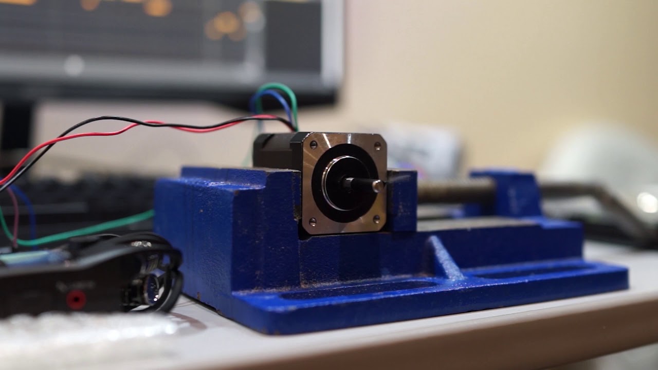
Here is a demonstration of a single stepper motor playing Yakety Sax:
Project Update April 15, 2022
A couple weeks ago, I received the custom PCBs for my ESP32 stepper and floppy synth. I also scavanged a free printer someone had thrown out. Similar to what the floppotron does with flat bed scanners. I will interface with the stepper motor inside the printer scan bed using the L298N H bridge driver. Im glad this printer has been saved from the landfill and will have a new purpose.
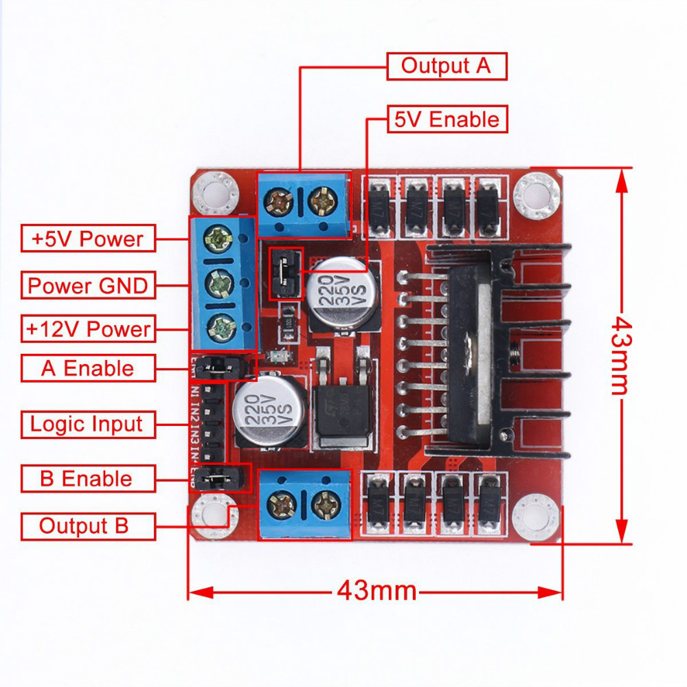
The L298N is designed to drive two DC motors with full direction and speed control. However, with some modification to the code, we can control stepper motors with the L298N. It is important that the stepper motor coil resistance is not too low(below 50 ohms) as this will cause the driver to overheat. If you choose to operate a stepper motor with resistances below 50 ohms, it is recommended to disable the driver as soon as the motor stops. Preferably, using a dedicated stepper driver(A4988, DRV8825) will be much more suitable.
To drive bipolar stepper motors with the L298N, place jumpers on the ENA and ENB pins. Next, identify the coil pairs in the stepper motor. Using a multimeter set into resistance mode, measure the resistance between any random two wires out of the four. If you get a very high reading (>1KOhm), then swap one of the leads with another and measure again. Do this until you identity the two coil pairs with resistance around 50-100ohms. Connect the coil pairs to the OUTA and OUTB terminals.
The programming is a bit more complicated because we need to pulse the IN pins in a specific order to step the motor. The forward ordering goes like this: IN1-IN3-IN2-IN4. To step the motor the other direction, we simply reverse the ordering. Here is some sample code:
void loop() {
    digitalWrite(IN1, HIGH);
    delayMicroseconds(2273); //Concert A
    digitalWrite(IN1, LOW);
    digitalWrite(IN3, HIGH);
    delayMicroseconds(2273);
    digitalWrite(IN3, LOW);
    digitalWrite(IN2, HIGH);
    delayMicroseconds(2273);
    digitalWrite(IN2, LOW);
    digitalWrite(IN4, HIGH);
    delayMicroseconds(2273);
    digitalWrite(IN4, LOW);
    delayMicroseconds(2273);
}