My journey with the NRF52
We are all familiar with the ESP32, STM32, and Arduino boards. They are very good hobby grade boards, but these are rarely used in production setups. I want to try to design a custom PCB that can fit in my wallet that has BLE, NFC, and RFID capabilities. Basically a DIY flipper zero. Lets get started:
Before I buy anything from Digikey or Mouser, I want to do as much prep as possible to reduce the workload. First, installing the toolchain and SDK. Nordic Semiconductor provides decent docs for this. At first, it can be confusing, but after reading it a few dozen times, I somewhat understand it. I am using Vscode as my IDE. There is also an extension called nRF Connect, but honestly I prefer the command line as its more familiar for me. Here are the refined steps I followed for a Unix based installation:
- Download
nrfutilhere,chmod +x nrfutil, and move it into/usr/local/bin. - Install the toolchain manager:
nrfutil install toolchain-manager - Install the toolchain. As of 01/10/25, v2.9.0 is the latest, specify the version you want:
nrfutil toolchain-manager install --ncs-version v2.9.0 - Start toolchain environment:
nrfutil toolchain-manager launch --shell - cd into the default toolchain directory:
cd ~/ncsIf you skip this,westwill install the SDK in the current directory. - Initialize SDK:
west init -m https://github.com/nrfconnect/sdk-nrf --mr main mainYou can specify a specific version by replacing first main with a version tag, 2nd main is the name of the directory created. - cd into the SDK directory:
cd mainDon’t skip this!! - Update:
west update. This takes a while. It pulls dependancies from GitHub and puts them into the current SDK directory. - Create cmake bindings:
west zephyr-export. Exports info for cmake into~/.cmake.
Note: If you get the error that
libunistring.so.2is missing, create a symbolic link:ln -s /lib/libunistring.so /lib/libunistring.so.2. Some Linux distros don’t includelibunistring.so.2by default,libunistring.sois the same(I think) aslibunistring.so.2, so we just symlink it.
If there are zero errors, congrats! You have installed the toolchain and SDK successfully. In VScode open the ~/ncs/main/nrf directory. If needed, replace main with the version of the SDK you specified. Now everytime we need to compile, we must start the toolchain environment in the terminal by running: nrfutil toolchain-manager launch --shell. This is really annoying every single time. In Vscode, you are able to define tasks by creating a json: .vscode/tasks.json. We run this task everytime the directory is opened, so we are automatically in the toolchain.
//tasks.json
{
    // See https://go.microsoft.com/fwlink/?LinkId=733558
    // for the documentation about the tasks.json format
    "version": "2.0.0",
    "tasks": [
        {
            "label": "Activate dev environment",
            "type": "shell",
            "command": "nrfutil toolchain-manager launch --shell",
            "runOptions": {
                "runOn": "folderOpen"
              }
        }
    ]
}
Now lets try building a sample project for the NRF52840dk. This is the development kit I will purchase after I finish designing the PCB.
- cd into sample projects directory:
cd samples/bluetooth/central_and_peripheral_hr - Build project:
west build -b nrf52840dk/nrf52840Specify the board using the-bflag.
If everything ran with no errors, the .hex file should be in the build directory named merged.hex. This is what will be uploaded to the board. Obviously can’t do that just yet, but don’t worry, I will document my experience when I receive the board. If there are any errors, make sure you are in the toolchain environment. Click the garbage can icon in VScode and execute nrfutil toolchain-manager launch --shell in a new terminal window and try again. Moving on, I want to write a program to blink an LED just to get familiar with the SDK. The documentation has good information on how this is done. We want to make a standlone application.
- Create a new project directory in the SDK directory:
mkdir -p projects/ledBlink,cd projects/ledBlink - Create src directory:
mkdir src,touch src/main.c - Create required dependancy files:
touch CMakeLists.txt,prj.conf,app.overlay
//CMakeLists.txt
cmake_minimum_required(VERSION 3.20.0)

find_package(Zephyr)
project(blink)

target_sources(app PRIVATE src/main.c)
//prj.conf
CONFIG_DK_LIBRARY=y
//main.c
#include <dk_buttons_and_leds.h>
#include <zephyr/kernel.h>

int main() {
    dk_leds_init();
    while (true) {
        dk_set_led_on(DK_LED1);
        k_sleep(K_MSEC(500));
        dk_set_led_off(DK_LED1);
        k_sleep(K_MSEC(500));
    }
}
Run the build commands specified earlier and to my surprise, no errors! A .hex file was generated in the build folder. Alright great, I am now somewhat familiar with the development. Lets go to the PCB design:
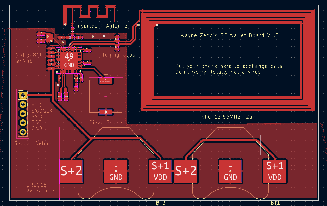
I am using KiCAD to design the PCB. Its open source, lightweight, and no bloody license key. I hate license keys, so annoying and I have to connect to the internet every single time to use the software. KiCAD also includes the majority of the features I need, so I don’t need to use software like Altium Designer. My plan is to use a 4 layer PCB, which allows me to get the correct impedances for the antenna traces. This board will have a 2.4GHz BLE antenna and a 13.56 MHz NFC antenna. These must be designed very carefully or the performance will suck. Here is the PCB I have so far:
The board stackup must also be configured correctly for your specified PCB manufacturer. I will be using JLCPCB for this project. When you order from JLC, you can specify a impedance control. If you select yes, you are brought to this menu:
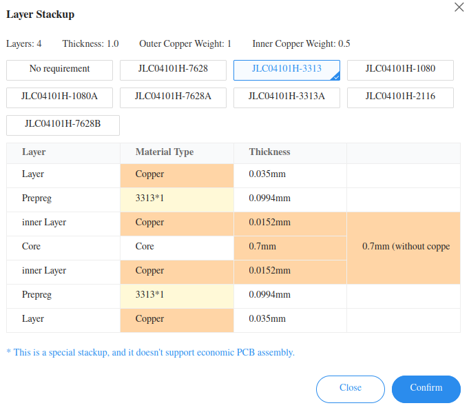
I will be using the default stackup JLC04101H-3313 because it allows me to use thinner traces to achieve the correct impedance. I don’t need to spent too much and its only the first prototype. You can see each layer and its thickness and configure them in KiCAD. Thickness for this PCB will be 1mm and the thickest point will be around 3mm due to the CR2016 battery holders. The next step is to calculate the correct impedance for the traces. We need a 50 ohm connection from the NRF to the 2.4GHz antenna and a 50Ohm differential trace to the NFC. JLCPCB also provides a controlled impedance calculator here. Simply put all the correct values on top and click calculate. We are using coplanar single and differential traces. Coplanar means on the same plane and surrounded by a ground plane. All my RF traces will be on the top layer.
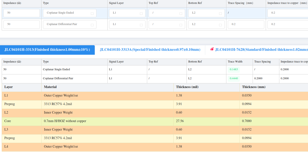
The trace spacing for the differential pair is the distance between them. You can configure this in KiCAD under Design Rules -> Net Classes. Of course the pin width is not 0.4mm, so the best we can do is get as close as possible to the NRF pins, then reduce the track width to 0.2mm. The impedance trace to copper is the distance from the RF trace to the outer ground layer. When you define the ground layer, you can tune this setting under Electrical Properties -> Clearance. Make sure this is 0.2mm or whatever you set. The impedance of the trace will change due to the prescence of a ground plane nearby. I simply use the inner layers as a ground plane to reduce noise and serve to match the impedance. If I use a 2 layer board, well I need a differntial track width of 3mm in order to satisfy 50Ohms, not super ideal in a small board like this one. I used a design from Texas Instruments called AN043. The document is a very good read and it provides exact specifications for the PCB antenna on page 4:
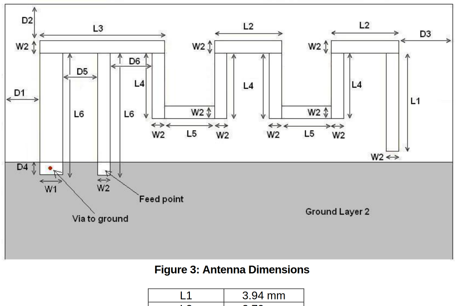
I used the footprint editor to create the antenna. Make sure to use square traces and set remove all technical layers. You want a solder mask layer on top and not have exposed traces.
I bought a NiceNano V1 and Xiao NRF52840 development board from Amazon. My goal is to blink an led, shouldn’t be too difficult. The issue is creating the board definition files for the Nicenano. Now the Nicenano is apparently a board for custom bluetooth keyboards. I found the relevant board files in the ZMK repository. In vscode, I created a custom board and simply copied the relevant file content over. At this point I am using v2.9.1 of the SDK, latest as of 05-07-25. The basic blinky example compiled with no problem. I put the Nicenano into DFU mode by shorting the RST pin to GND until the red led blinks slowly. Then drag the generated uf2 file under build directory to the mountpoint. Every time I upload the uf2 file, the red led blinks rapidly, which means the board is crashing. FOR WEEKS I WAS STUCK ON THIS, TRYING OUT DIFFERENT CODE, I EVEN BOUGHT A XIAO BOARD, BUT I GAVE UP.
Sike, jk. After a couple days of rest I decided to try again, but I downgraded the SDK to v2.2.0. Compiled, dragged the .uf2 file onto the board and BOOOOMM!!! Led started to blink on both the Xiao and Nicenano!!!! USB uart doesn’t work on Nicenano, but thats ok. I AM SO RELIEVED I FINALLY got it working. As of 2025-05-07, I will put this project on hold until I finish my STM32 project. I might try playing with Zigbee on the NRF52840dk and of course turning one of these boards into an Airtag using Macless Haystack project.